Circuit description
This programmer is custom made for the Xicor 28C16 EEPROM, for other manufacturers please check the specification
because the pinning is not always the same!
For the XICOR pinning see the Xicor 28C16 specification (86kB) (right click to save this pdf file)
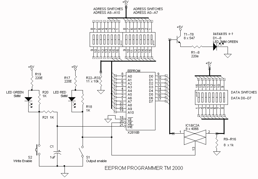
The 11 adress bits are set by 11 DIP-switches (A0--A10);
The 8 data bits (IO_0--7) can be set by 8 DIP-switches, the data can be monitored by 8 green 3mm LED's
which are fed by 8 transistor buffers
When the outputs of the EEPROM are enabled, the 8 data-DIP-switches are disconnected by 8 CMOS switches (2 x 4017 IC)
The output enable is set by switch S1, when the RED 5mm LED lights up, the data outputs are enabled.
The write enable is set by switch S2, when the green 5mm LED lights up, the EEPROM is in write mode.
The real write cycle is started when the Write Enable pin becomes high: the 1uF/1k resistor will prevent switch bounce on this signal.
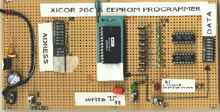
Picture of assembled EEPROM programmer
Manual EEPROM programmer schematic:
EEPROM programmer manual
The use of the programmer is quite easy, just strictly follow the lists below:
To program data:
· SWITCH OFF S1: Data terminals D0--D7 are set as input
· INSERT THE EEPROM IN THE SOCKET
· SET DATA SWITCHES 0--7
· SET ADRESS SWITCHES 0--10
· NOW DEPRESS S2 FOR ABOUT ONE SECOND (GREEN LED ON FOR ONE SECOND)
Now the data is programmed into the EEPROM at this adress. To verify this, you can read the data as described below:
To read data:
· SWITCH ON S1: Data terminals D0--D7 are set as output
· INSERT THE EEPROM IN THE SOCKET
· SET ADRESS SWITCHES 0--10
· READ THE DATABITS D0--D7 FROM THE 8 GREEN 3MM LEDS
EEPROM programmer manual
The use of the programmer is quite easy, just strictly follow the lists below:
To program data:
· SWITCH OFF S1: Data terminals D0--D7 are set as input
· INSERT THE EEPROM IN THE SOCKET
· SET DATA SWITCHES 0--7
· SET ADRESS SWITCHES 0--10
· NOW DEPRESS S2 FOR ABOUT ONE SECOND (GREEN LED ON FOR ONE SECOND)
Now the data is programmed into the EEPROM at this adress. To verify this, you can read the data as described below:
To read data:
· SWITCH ON S1: Data terminals D0--D7 are set as output
· INSERT THE EEPROM IN THE SOCKET
· SET ADRESS SWITCHES 0--10
· READ THE DATABITS D0--D7 FROM THE 8 GREEN 3MM LEDS

